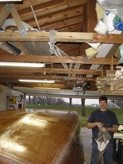
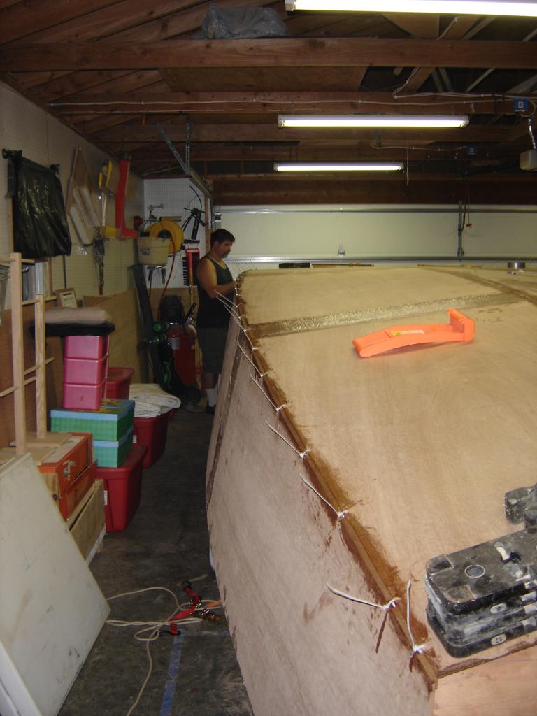
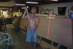
We laid some more glass yesterday, but I'm going to digress a bit.
You may remember in an earlier post that we had a couple of spots where the fiberglass didn't adhere to the plywood. Our initial plan was to drill small holes in these areas and fill them with epoxy. Greg changed his mind. Instead, he cut out these areas with a knife, and filled it with a mixture of epoxy and fiberglass filler. My camera batteries were dead, so I don't have any pics of this, but I will attempt to get some pics posted soon.
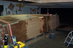
After the fiberglass filling, we did a little last-minute sanding, and laid fiberglass on one side. We've now got about two-thirds of the exterior completely fiberglassed. We still have one side, and both transoms to do, but that should go relatively quick. Of course I'll post pictures.
Monday, December 26, 2005
Saturday, December 17, 2005
Other Uses for Epoxy and Plywood - Part IV
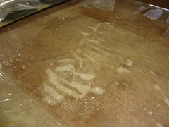
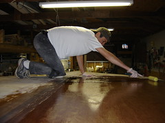
In this photo, you see that I've done part of the bottom, or side, section. I was fortunate that this section came off in one large sheet, so I didn't have to re-lay individual tiles. The hardest part of re-laying the tiles comes next. Wish me luck.
By the way, if you're interested, you can also see my other home improvement project on my other blog. I figured that it was more appropriate to post this project here, since it so heavily utilizes plywood and epoxy.

By the way, if you're interested, you can also see my other home improvement project on my other blog. I figured that it was more appropriate to post this project here, since it so heavily utilizes plywood and epoxy.
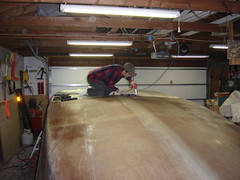
Other Uses for Epoxy and Plywood - Part III
You can see that I've used thickened epoxy and laid the tiles on the top section. It's not pretty, but it's functional - and waterproof. I plan to drill out the epoxy between the tiles and re-grout. That will make things less ugly.
Other Uses for Epoxy and Plywood - Part II
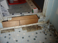
In this picture, you see that I have installed the scrap plywood. the plyowood has been sealed with epoxy, so it should stay waterproof for until I truly remodel this bathroom. I've screwed it all into place with waterproof screws, and you may see that I've test-fitted a block of tiles.
Thursday, December 08, 2005
Other Uses for Epoxy and Plywood
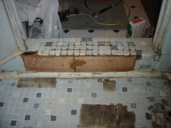
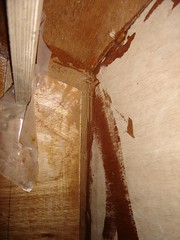
 By now, we're all familiar with using epoxy and plywood for building boats. But have you considered using plywood and epoxy for other jobs around the house? The previous owner of my house installed a tile shower, and used plain plain 2x4's and plywood for this water-catching lip. Over the years, water has gotten in here, and eventually it rotted away the plywood and the wood.
I'm not going to the trouble of completely ripping this out and starting from scratch, but I am going to repair it so it stays put until I'm ready to completely overhaul this bathroom. Enter the epoxy and plywood...
During the course of the next couple of weeks, I am going to epoxy the remaining wood, in an attempt to prevent any further deterioration. I will cut some scrap plywood to size and lay a protective layer of epoxy over that as well, which will waterproof the entire base. Finally, I will use thickened epoxy to stick the tiles back into place. Why epoxy instead of cement? Because I have the epoxy and plywood available. I'd have to go out and buy the cement. The only reason NOT to use wood is because of the rotting factor. By coating it all with epoxy, I have removed the potential for rotting.
Overall View
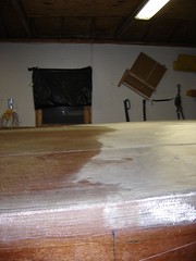
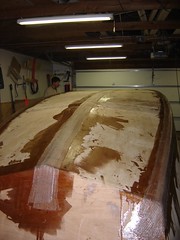
As you can see, our work paid off in the end. For the most part, it looks really good, and you can't really tell where we ran out of epoxy.
Next time we'll lay epoxy on the sides, then it's time to start fairing and sanding.
Next time we'll lay epoxy on the sides, then it's time to start fairing and sanding.
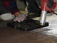
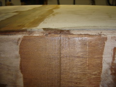
Drilling Small Holes
We're overcoming our problem by drilling small holes where the epoxy bubbles are. We will then inject epoxy into the holes and weight down the area, so the fit is as tight as possible in the end.
The Journey Continues
You may remember from our last couple of entries that we ran out of epoxy. In order to overcome this potentially disasterous problem, we heated the cured epoxy with a heat gun, and applied epoxy to the rest of the boat.
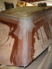
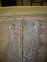
This picture shows that, for the most part, our approach worked incredibly well. However, also shown in the picture, we had a few spots that were completely starved and didn't adhere to the hull at all.
How did we overcome this problem??? Read on and find out.
This picture shows that, for the most part, our approach worked incredibly well. However, also shown in the picture, we had a few spots that were completely starved and didn't adhere to the hull at all.
How did we overcome this problem??? Read on and find out.
Tuesday, November 29, 2005
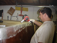
Heating Fresh Epoxy
There were a couple of areas on the rear transom where the glass didn't lay down to our liking. Greg decided to see if heating the epoxy in this area would work. After a few minutes, we discovered that the epoxy got very thin and dripped a lot. This tended to starve the fiberglass, didn't help the fiberglass adhere to the plywood at all, and the epoxy that remained in the fiberglass had dried enough to touch after a mere five additional minutes.
In short, I don't recommend using a heat gun on uncured epoxy. It's a good way to give yourself a second chance on cured epoxy though. In fact, I'd call it a sheer stroke of genius on Greg's part.
In short, I don't recommend using a heat gun on uncured epoxy. It's a good way to give yourself a second chance on cured epoxy though. In fact, I'd call it a sheer stroke of genius on Greg's part.
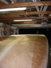
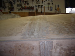
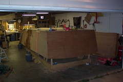
Glassed Bottom
The rest of the bottom has been glassed. As I write today's entry, we're waiting for the epoxy to completely cure. This weekend, we'll touch up any areas that need it, do a little sanding, and lay glass on the sides and transoms as needed.
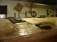
Weighting the Transition Area
To help ensure a good bond in the area where we ran out of epoxy, we laid a slightly thicker layer of epoxy, then laid a sheet of plastic over the transition area, laid a piece of plywood over all of that, and weighted it down. From the transition point on, we epoxied as normal.
Quick Heating and Quick Cooling
As mentioned in the last entry, we used a heat gun to heat up the stiff fiberglass, and soften the epoxy. Immediately upon softening, we laid a cool metal weight on top of the newly-softened fiberglass. This helped the fiberglass lay flat as it should.
As we went, we learned that we could run the heat gun in front of the weight, which would heat the fiberglass and epoxy, and we could immediately slide a weight behind the heated area. this would ensure the area would lay flat. I've gotta say, it was a pretty clever trick.
As we went, we learned that we could run the heat gun in front of the weight, which would heat the fiberglass and epoxy, and we could immediately slide a weight behind the heated area. this would ensure the area would lay flat. I've gotta say, it was a pretty clever trick.
An Answer to our Glassing Problem
We ("we" being Greg for the most part) thought about possible solutions for our problem on how to get the partially-wetted fiberglass to properly adhere to the hull. After a week or so, Greg found the answer. We used a heat gun and softened the epoxy in the areas where the fiberglass was bubbled up from the hull.
Friday, November 18, 2005
A Stroke of Luck?
Here's the answer from bateau about our epoxy problem.
---Begin Original Text---
If you can get it to wet out, there should not be any problems. The larger white areas are going to be easy, its the spots that have been half way wetted out that will be diffucult to make right - you will have to really work the epoxy into the glass to wet out the dry fibers.
---End Original Text---
They asked for some close-up pics of the area where we had run out of epoxy, (here are links to the pictures 1 2 3 4 5 6 7) they talked among themselves, and the concensus was that we could probably do it, but it would take work.
Note: These pics are very large. They'll take a minute or so with broadband. If you're using dial-up, make lunch while you wait for the downloads.
Hey, I can handle a little extra work. I was concerned that we'd have to cut the cloth, toss out the stuff that wasn't epoxied thoroughly, sand down the transition area, and relay the back section; which would have cost us several extra hours of work and about $50 to $100 in extra fiberglass.
Greg came to the conclusion that we really did have enough epoxy for the job, but we used a grout float instead of a squeegee when we applied the epoxy. After looking at the boat, there's little doubt in my mind that he's right. I agreed with his assessment when I saw how much epoxy had run down the side of the boat. Using a squeegee was easier and faster, but it cost us extra in the long run. Greg had to buy more epoxy than originally anticipated, and it's going to cost us a little extra work. I wouldn't disrecommend using a grout float for the big jobs; in fact I'd still recommend it. But I would also highly suggest that you double your estimate when you consider how much epoxy you'll need for the job. The worst that will happen is that you end up with extra epoxy, which can be used on your next job.
As usual, I'll take more pictures (heck, maybe I'll do a video... we're about due for one) and update you on the progress.
Sunday, November 13, 2005
A Significant Setback on our way to a Major Milestone
We ran out of epoxy. Between applying the base coat to the bare wood, and the bonding coat that bonds the glass cloth to the hull, we went through well over three gallons of epoxy.
This could have some major unintended side effects for us, but I'm not sure yet.
The front half of the boat is fine. I'm not so sure about the back half. Greg thinks that we can just get more epoxy and continue where we left off. I'm concerned that we'll need to rip up the cloth that didn't get bonded and reapply the cloth. Here's what I'm thinking...
We've got the base layer of epoxy applied to the bare wood. It's also ever-so-slightly bonding the fiberglass cloth to the hull. But I'm concerned that it's not quite right. I'm going to ask Jacques over at the boat forum and get his input. I'll let you know when I get the answer.
Glassing the Hull
This picture shows the front half glassed and epoxied. If you look closely at the picture, you can see the line where there's no top layer of epoxy.
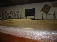
Prepped Hull
The hull is now prepped. A base coat of epoxy has been applied to the entire exterior of the hull. Isn't it shiny?
Prepping the Hull
Yesterday we started the process of laying fiberglass cloth on the hull. Here's a picture of me rolling a base coat of epoxy onto the bare wood of the hull.
Finished Taping the Seams
Greg got the front and rear transom joints taped. The corners have six layers of fiberglass on them. They should be able to withstand a direct blast from a nuclear warhead.
Sunday, November 06, 2005
Another Minor Milestone
We haven't done much the last couple of weeks, because my wife and I went on our honeymoon. Greg did a little work while I was gone, but not a whole lot... mainly a few last-minute things before doing what we did last night... laying tape!
That's right, we laid tape on the three long seams. Greg said that he'd to the transoms today, so we have not only a good physical bond, but a good chemical bond with the epoxy as well.
That's right, we laid tape on the three long seams. Greg said that he'd to the transoms today, so we have not only a good physical bond, but a good chemical bond with the epoxy as well.
Tuesday, October 18, 2005
Resolution to the Errors We're Experiencing
We received an answer that thoroughly answers the questions regarding the fit problems we've encountered while assembling the hull. The short answer is that it's a combination of problems with how the kit was cut at the factory, and assembly error. If you're interested in the long version, I'm attaching the response from Jacques, one of the admins at www.bateau.com
---begin original message---
Here are Ryan's conclusion[s] and I agree with them. We have looked many times at this and suspected a problem if parts were cut from the nesting drawing. We found only discrepancy . Ryan's notes are in italic. My comments are in blue.
-----------------------
"The aft pieces of the hull bottom were too wide where they meet the middle pieces of the hull bottom. I laid out the plan spec dimensions on these pieces and had to cut off slivers approximately 5/8" wide, tapering down to 0", by 20" long, in order for these pieces to meet the plan specs and to get them to butt properly to the middle bottom hull sections. The cuts were on the outside of the pieces."
---->I have no clue about this. The nesting matches the dimensions.
That must have been a CNC machine problem. Fortunately, it was too large and easy to correct.
2) The aft and bow transoms were mounted on the building frame, at the distances and angles specified in the plans. A laser was used to precisely align everything. When the glued and assembled stringers were put in place, it was clear that they were about 3 inches shorter than the distance between the transoms. Part of this distance (1/2") can be explained by the fact that I did not account for the front cabin bulkhead fitting between the aft and bow portions of the stringers, as I had glued them up as one contiguous unit (instead of installing the bow portion of the stringers later, as indicated in the on-line building tutorial). However, having to recess the stringers 1/2 way into the transoms adds 9/16" for the bow transom and 1" for the aft transom (which is 2" thick for large motor usage). This adds up to: 3" - 1/2" + 9/16" + 1" = approximately 4 inches that the stringers were short. I do not recall what the exact measurements are, and I did not try and crawl under the boat to take them again. Thus, I cannot say whether this is a plan or kit error."
---->the kit: The transom that was in the nesting was too big. It was about 1-7/8" too big. The stringer tips in the nesting were about 1" too short.
The CNC file for those parts was taken from the nesting drawing but the nesting drawing is not to scale!
You corrected properly.
"This problem was corrected by moving the bow transom aft the proper distance so that the stringers would fit right. I knew this could change the way the bottom panels fit, so when we put the aft 3 building molds in, we reduced the distance between each of them a small amount. This was done because the bottom is much flatter in this area and I knew it would affect the shape/fit of the panels less than adjusting each mold position or just the front ones."
--->Once they do this.....the frames won't fit right.
That looks like an assembly mistake you made but again, you corrected it properly.
"Some of the kit frames were not wide enough. For example: According to the plans, Frame F should be 90-1/4" wide. The actual measurement is 88-1/4". Frame E should be 92-3/4", and the actual measurement is 90-3/4"."
---->The nesting matched the station dimensions....so I don't know about this.
Me neither . . . were those frames marked correctly?
"Several of the kit pieces that were supposed to be 3/8" plywood were actually 1/2". I have been able to work around this without too much problem and the small amount of extra weight should not affect the performance."
---->Not sure about this one either.
I discussed this with Eric. he asked permission to use 1/2" instead of 3/8 for cutting reasons. I checked and gave the OK, it has no effect on weigth (maybe 5 lbs total!) and can only be better question of strength.
-----------------------
Conclusion, it looks like there were some problems with the kit, some I understand, others not but you solved the problems. Sorry for those cutting mistakes. Email when you need paint or other supplies, we'll do something special.
All the dimensions on the plans are correct, it's a kit problem that does not affect those building from the plans. Eric and I have discussed this. In 95% of the cases, despite what we say on the plans (NTS = Not To Scale), our plans are to scale. Those parts were an exception. Right now, we do not cut kits from the nesting drawing anymore.
_________________
Jacques Mertens
---end original message---
My personal opinion on the whole deal...
The root of the problems were based on errors in the kit. The problem was exacerbated when we adjusted our assembly process upon encountering kit errors, resulting in a chain reaction of minor, correctable issues.
Jacques and crew have been instrumental in figuring out the root of the problem, and there's no doubt in my mind that they'll work with the kit manufacturer to ensure this doesn't happen again. Additionally, they appear to genuinely care about customer satisfaction, as evidenced by their promise to "do something special" next time we order supplies. Despite the fact that we've experienced these minor setbacks, I have been satisfied in my dealings with these guys, and I would freely recommend bateau for anyone who is building a houseboat (or any other type of boat.) "If you're building a houseboat, go to www.bateau.com for the plans, kit and supplies."
By the way, if you do end up ordering from bateau as a result of reading this blog, tell 'em that OzzyC sent you.
Sunday, October 16, 2005
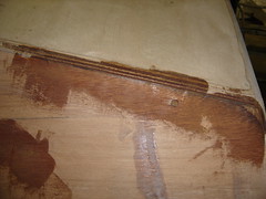
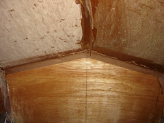
Bad Epoxy Joint
We also went over the taped joints one last time. This one was the worst. There was a large gap in the joint. The gap had no epoxy in it, and the tape had bonded poorly at the seam. We cleaned things up and filled the joint with thickened epoxy.
Not a single tape joint was truly smooth. There were "waves" in the epoxy, so we smoothed it all out by laying thickened epoxy, using a sqeegee.
Not a single tape joint was truly smooth. There were "waves" in the epoxy, so we smoothed it all out by laying thickened epoxy, using a sqeegee.
Patched Front Transom Gap
We went around the entire boat and patched all gaps, holes, gouges, and so forth, with thickened epoxy.
...and Then I Went to Help Greg...
... work on his boat.
This week we did a final laying of thickened epoxy, in preparation for taping the seams.
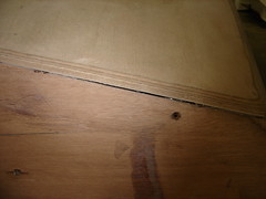
In this photo, you will see a small gap between the transom and the hull, and a screw hole.
This week we did a final laying of thickened epoxy, in preparation for taping the seams.
In this photo, you will see a small gap between the transom and the hull, and a screw hole.
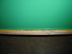
Flaw in the Rubrail
In a continuation of "back to basics" week, I will discuss this rubrail in a bit more detail.
We purchased 10-foot sections of oak, which is obviously too short for the entire canoe. We compensated for this by angle-cutting the oak sections and joining them together with epoxy. We did the joints at port-bow and starboard-stern, for load balancing. This way if we hit something that would break one joint, they both wouldn't break.
This spring, my boat hit a rock in rapids, and popped the rubrail joint. I tried patching the popped joint with gorilla glue, but that was inadequate for the job, and the joint popped again, (on a much smaller rock, at a much lower speed.)
As you can imagine, I was starting to get a little frustrated over my canoe continually "breaking." I figured it was time to do the job right, so I decided to sand and re-epoxy the joint from scratch.
Unfortunately, my daughter wanted to help, and due to a perfect storm of circumstances, I didn't quite mix the epoxy right, and it never quite set. Growing even more weary of this ongoing problem, I sunk a couple of bronze nails into the seams, figuring that would do it. That's when I sanded and painted the boat, and when I noticed the flaw in this picture. If you look VERY closely (not the best picture), you can see that there's no epoxy bonding the rubrail to the hull. Once the paint dries, but before I stain the rubrails, I will bond the rubrail to the hull with a thin line of unthickened epoxy.
Back To Basics
Building the Nice Canoes was our experiment. We built the canoes first, so we could get an idea of how much work building the GT-23 would be, and to make sure we were up for that kind of work.
I've had my canoe for about a year and a half, and I've used it a LOT. She was starting to show her age...
It was time for a new paint job. I sanded down the entire exterior, including the rubrails. This photo shows the paint job. Today or tomorrow I'll do a bit more painting, a little touch-up, and then it's into storage.
Wednesday, October 05, 2005
Answers to Questions
As I mentioned in my last post, Greg asked a couple of questions about planing a swath along the seams, so the fiberglass lays flush to the hull after laying the fiberglass, as opposed to building up the layers of fiberglass, then fairing... thus saving us some sanding. Bateau recommended that we not do this. Here are a couple of other links that discuss the recommended methods of taping and sanding the seams...
Stitch and glue basic tutorial
Outside fiberglassing
Stitch and glue basic tutorial
Outside fiberglassing
Monday, October 03, 2005
Video Synopsis
It's been a while since we've made any significant progress on the boat, so we haven't done any videos for a while. In commemoration of what we've accomplished this weekend, we did a video. If you're interested, click here.
We plan to build the keel up one more time, and sand again, just to make sure we've got a straight line, and to make sure it's properly filled before we lay the fiberglass. If you're interested in seeing our plan for that, click here.
We plan to build the keel up one more time, and sand again, just to make sure we've got a straight line, and to make sure it's properly filled before we lay the fiberglass. If you're interested in seeing our plan for that, click here.
SandedHull
All of the seams are now sanded and rounded. We've got a procedural question in to the gurus about taping the corners. Apparently, some people plane the hull where the seams are, and the result is a lot less sanding. We'll let you know when we find out.
Trimmed Transom
Greg got the overhang trimmed from the front and rear transom, using a jigsaw. It looks a lot better now.
Monday, September 19, 2005
Clarification on the Errors We're Experiencing
I received a message from one of the administrators at bateau, requesting that I clarify something about the errors we're experiencing.
There are three possible places where these fitting problems could be occurring. Those places are the plans themselves, the kit, or how we as builders are executing these plans (or any combination thereof). At this point I honestly don't know the root cause of the issue. I will say unequivocally that the administrators at bateau have been incredible about working with us when we've experienced problems, and I will clarify for the record that it's highly possible that the issues are due to what we're doing and how we're doing it, as opposed to it being a problem with the plans or the kit we purchased.
Please do NOT take the contents of this blog as any intent to question the quality of the plans that bateau produces, nor the kits that they manufacture. This blog is designed to look at the building process... nothing more.
Sunday, September 18, 2005
A Nod to the Designer/Architect
In my last post, Dr. Howdy has (quite rightly) recommended that I give some credit to the designer/architect of this fine boat. Greg purchased the plans from www.bateau.com. I will work to find out more about the individual who designed this boat and will post as the designer deems fit.
Front Transom - Inside
This is the front transom from "inside" the boat. Again, the purpose of this round of work was to fillet the front and rear transoms. If you notice at the top center of this pic, the thickened epoxy dripped. Why??? Because we were too lazy to run to the store for good duct tape. we used package tape instead, it didn't hold, and the peanut butter oozed through. This will cost us a lot more work in the long run, when it's time to sand.
Filleting
In this picture, we are filleting the gap between the hull and front transom. In the picture you will notice the large gap filled with thickened epoxy. You see the stringer in the left-top of the picture, and you see that the stringer is covered with plastic, in order to prevent the stringer from sticking to the transom or hull during the epoxying process.
Another Shot of the Hull
In this picture, we've still got weights on the front end, because we haven't filleted the inside transom joints with thickened epoxy yet.
Coming Along Nicely
We've got the joints epoxied, and the zip ties are pulled out. You may notice a couple of sloppy tape joints. We'll need to fix them before we glass the whole boat. If you click on the picture, you'll be referred to flickr, where you can see a larger picture, and a note pointing out the sloppy tape joint.
Front Transom Overhang
The overhang on the front transom is more pronounced than the rear transom. Again, the hull extends past the front transom.
Though this makes for a bit more work, I'd rather have the pieces measure too large than too small. It's a lot easier to cut away the excess than it is to build on a piece that's too short.

Though this makes for a bit more work, I'd rather have the pieces measure too large than too small. It's a lot easier to cut away the excess than it is to build on a piece that's too short.
More Flaws in the Plans
This is a picture of where the hull and rear transom come together. If you look, you can see that the hull extends past the transom. In addition to this, we've discovered that the rear transom was also too wide, and we've had to shave some width from the port and starboard sides of the rear transom.
Sunday, August 28, 2005
Tying the Hull
We've finally had an opportunity to get back to work on the boat. The weather was cool, our schedules were clear, so we worked. Last night we spent about three hours tying the hull and filling the gaps with thickened epoxy.
Monday, August 08, 2005
I Haven't Forgotten About You... or the Boat
We didn't do any boat work this weekend. Greg was out of town. We're probably not doing any boat work next week because it's gonna be my bachelor party. We won't be doing any boat work the weekend after becaust I'm getting married that weekend, and it's Greg and his daughter's birthdays. Are you seeing a trend here? I miss working on the boat.
But last weekend, we joined the bottom hull pieces together with thickened epoxy. Not much progress, but every little bit counts.
But last weekend, we joined the bottom hull pieces together with thickened epoxy. Not much progress, but every little bit counts.
Saturday, July 23, 2005
Crazy from the Heat
Like I said in my last entry, this heat's a killer. We started at around 7:30 and put in about 2 and a half hours. What did we accomplish? Unfortunately not too much.
When we did our test fit last weekend, we saw that the bottom panels were about two inches too wide. So this week we (actually it was just Greg) built a jig so we could draw a line along the hull without removing the sides that we'd strapped on, and then we ran a circular saw along the length of the bottom panels and shaved off the extra. In short, we finished about 1/2 hour worth of work in about 2 and a half hours.
When we did our test fit last weekend, we saw that the bottom panels were about two inches too wide. So this week we (actually it was just Greg) built a jig so we could draw a line along the hull without removing the sides that we'd strapped on, and then we ran a circular saw along the length of the bottom panels and shaved off the extra. In short, we finished about 1/2 hour worth of work in about 2 and a half hours.
Thursday, July 21, 2005
Make Sure to Use Plenty of Epoxy
After we cut the excess length off of the rear transom, we decided to test the strength of the epoxy. I figured a drop test would be the best way to get a guage of how strong our gluing job was, and I was concerned with the results.
I dropped the excess from about five feet, to see how well it would hold up to a shock. The results weren't good. One of the four layers completely broke away. The second layer, as shown in this picture, split about 2/3 of the way through.
The moral of the story?? Use more glue than we did. In order to compensate for the lack of glue, we are going to reinforce the rear transom with several bronze screws. We're going to use bronze screws because they won't corrode over time.
The Kit Isn't Perfect
In this photo, I'm holding the piece we cut from the rear transom. We cut this piece from both ends, so the kit cut the rear transom about 1" large on both ends.
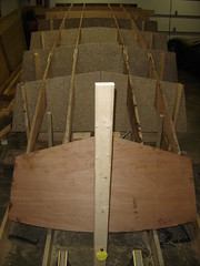
What a FLAT Boat
This shot gives a good idea of how flat and square this boat is. Looking at it from the back, it almost looks like a cube.
Fits and Starts
After what seems like an eternity without doing anything on the boat, Greg and I finally got some time to work on it -- not much, but in such a major undertaking, every little bit counts. The biggest obstacle right now is the heat. Greg's garags isn't climate controlled, so with the latest heat wave we've been having, it's easily over 100 degrees in the garage until late in the evening. This, naturally, slows the progress.
On Saturday evening, we finally test-fitted the sides of the boat. Though the photo doesn't show it well, the bottom of the boat sticks out a little bit over the sides, so we're going to have to do a little trimming before we can stitch the hull together.
On Saturday evening, we finally test-fitted the sides of the boat. Though the photo doesn't show it well, the bottom of the boat sticks out a little bit over the sides, so we're going to have to do a little trimming before we can stitch the hull together.
Monday, June 27, 2005
Dammit! Two More Weeks of Lost Productivity
I was hoping that we'd be able to spend Saturday or Sunday working on the boat, and that we could spend a marathon day over the 4th of July weekend. But alas, that wasn't in the cards.
Greg was out of town Saturday and most of Sunday last weekend, and he's got plans next weekend too. By the time we get back to the boat work, we will have gone six weeks with out any significant progress. While our goal was to put in one good day per week, and we realized that we'd periodically miss a week here and there, I didn't expect that we'd go this long without any progress. I sure want to get back to work.
Greg was out of town Saturday and most of Sunday last weekend, and he's got plans next weekend too. By the time we get back to the boat work, we will have gone six weeks with out any significant progress. While our goal was to put in one good day per week, and we realized that we'd periodically miss a week here and there, I didn't expect that we'd go this long without any progress. I sure want to get back to work.
Saturday, June 25, 2005
Test-Fitting the Hull
When I said that it had been over three weeks since we'd accomplished anything on the boat, I wasn't completely accurate. I did go over to Greg's place last weekend, and we did the finishing touches on the frame, and test-fitted the bottom hull pieces. As you see in the photo, the hull pieces are too long. They're also a little too wide, and the rear transom is a little too wide, so we're going to have to do a little trimming before we can zip-tie the hull and start glassing the boat.
For a closer look at the overlaps I'm talking about, you can click here for a close-up of the front transom/hull overlap. This link will give a closer view of the overlap along the sides, and this link will give you a better idea of how far off the rear transom is.
Time Flies
Man, I can't believe it's been over three weeks since I've updated this blog. Even worse, I can't believe it's been that long since anything has been accomplished on the boat. The lack of progress will hopefully come to an end tomorrow though, as Greg and I get back into the swing of things. I'm a little disappointed that our progress has stalled, but it's because I've been out of town, so I'll cut myself a little slack... of course there's nothing that's prevented Greg from working on the boat while I've been gone, but that's another story.
I've already discussed the Boys' Trip we had over Memorial Day weekend, but I haven't mentioned my family vacation to the Buffalo, NY area. That trip was a blast, but it's a little off-topic for this blog. If you're interested in reading about it though, feel free to head on over to my other blog.
I've already discussed the Boys' Trip we had over Memorial Day weekend, but I haven't mentioned my family vacation to the Buffalo, NY area. That trip was a blast, but it's a little off-topic for this blog. If you're interested in reading about it though, feel free to head on over to my other blog.
Wednesday, June 01, 2005
A Well-Deserved Vacation
As I mentioned in last week's post, we took the week off so we could attend our annual guys week vacation. Click here to view the pictures. You can also see a short video of Dave surfing Gilmore's Mistake on the Wolf River, or a video of kids rafting the Wolf River.

Monday, May 23, 2005
The Frame is Finished
Yesterday Greg and I put the finishing touches on the frame -- unless he decides to re-tweak, which he often does. We shimmed all of the areas where there were loose joints on the temporary frame. We're now ready to lay the hull. Next week, we will be in Northeastern Wisconsin, for our annual canoe/whitewater kayak trip, so there won't be any working on the boat. Instead, we'll be playing in the canoes we made last year and paddling our kayaks.
Sunday, May 15, 2005
Another reader question
Here's another question/comment from Squid.
---Begin Original Comment---
Looking good guys, did you order the pre cut kit for this boat? Do yo think it saved you a bunch of time? I don't think I could afford to get the kit for one of these big boats I would probably get enough wood at a time to do the hull and then buy more for the rest. keep up the great work guys you inspire me. can't wait till I build my next boat. It will either be this one or the HB-20, possibly stretched to a 22 (feet). You can strech by 10 percent.
Squid
---End Original Comment
Yessir, we did order the precut kit, and there's no doubt in my mind that it's saved us a boatload of time. (I hope you'll forgive the irresistable pun.) It saved us the hassle of measuring the dimensions of each piece -- and remeasuring, because we're picky. It saved us the time of cutting each piece by hand, because they pre-routed everything, leaving us just small tabs to cut, and the kit may have even saved Greg some money, because he likely would have wasted more wood than the makers of the kit did. Okay, it didn't save any money, but it definitely saved us a lot of time. The big benefit of buying the kit is saving time. The biggest benefit of cutting the pieces yourself, as you alluded to, is that you can spread the cost out over a longer period of time by buying stuff as you need it.
Saturday, May 14, 2005
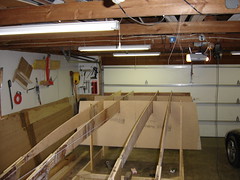
It's starting to look like a boat
This week, we set the rest of the sacrificial frame pieces in place, using the same process described in last week's entry. This photo shows the full skeleton of the boat, and based on the shape of the skeleton, you should now be able to mentally picture the shape of the hull.
At this point, the stringers and sacrificial frame pieces are not precisely set in their final position, but they're pretty close. Some of the notches are too wide, too deep (or too shallow), or some combination thereof. But again, it's pretty close.
Next week we will do more precise adjustments of the frame by cutting the too-shallow notches a little deeper, and shimming the areas where there's too much slop. That process will likely take a couple of sessions, because we're picky on precision.
Sunday, May 08, 2005
Question/Comment from a reader
The following is a comment from Squid, a member of the forum at www.bateau.com
---Begin original comment---
[S]hure looks like a flat bottomed boat at the transome end. How do you think it will handle in the chop and wind. I know they have wind in Iowa. I am interested in building this boat but will wait till you have yours done and can tell me how it handles. Squid.
---End original comment---
This is a valid point, and one that I honestly hadn't considered. But even if I had, this boat actually belongs to my friend Greg, so I didn't have much input on which plans were actually purchased. I'm just the first mate. (Call me Gilligan.) Now that the point is brought up though, here's my take.
You're absolutely correct, this is a flat-bottomed boat. The result is that it will probably rock-n-roll a little more in choppy water, but I wouldn't worry about that a whole lot. It's going to be a big, heavy boat, so I suspect that it'll take quite a bit to make the boat roll excessively. As far as the wind goes, I don't think it'll be a huge factor. The rear transom isn't much different from your standard power boat, so I suspect the amount of surface area that the wind could catch is probably comparable to a standard displacement hull. The front transom is relatively small, so I don't see wind as a factor here either, and the same goes for the sides. Besides, it's not like we're rowing this big-ass boat. Greg's going to put in a couple of big motors to do the work for us.
In short, the only way I see wind being a factor is when the wind causes waves on the water, in which case the boat will probably rock a bit more than a displacement hulled boat.
The picture Squid's referring to is shown earlier in the blog, but you can click here for a direct link to the picture.
---Begin original comment---
[S]hure looks like a flat bottomed boat at the transome end. How do you think it will handle in the chop and wind. I know they have wind in Iowa. I am interested in building this boat but will wait till you have yours done and can tell me how it handles. Squid.
---End original comment---
This is a valid point, and one that I honestly hadn't considered. But even if I had, this boat actually belongs to my friend Greg, so I didn't have much input on which plans were actually purchased. I'm just the first mate. (Call me Gilligan.) Now that the point is brought up though, here's my take.
You're absolutely correct, this is a flat-bottomed boat. The result is that it will probably rock-n-roll a little more in choppy water, but I wouldn't worry about that a whole lot. It's going to be a big, heavy boat, so I suspect that it'll take quite a bit to make the boat roll excessively. As far as the wind goes, I don't think it'll be a huge factor. The rear transom isn't much different from your standard power boat, so I suspect the amount of surface area that the wind could catch is probably comparable to a standard displacement hull. The front transom is relatively small, so I don't see wind as a factor here either, and the same goes for the sides. Besides, it's not like we're rowing this big-ass boat. Greg's going to put in a couple of big motors to do the work for us.
In short, the only way I see wind being a factor is when the wind causes waves on the water, in which case the boat will probably rock a bit more than a displacement hulled boat.
Mounting Frame Pieces
We've begun to mount the horizontal (port-to-starboard) frame pieces. There are six in all, and yesterday we mounted three.
We started by temporarily removing the stringers. This was Greg's idea, and I saw no need to keep them mounted, so they were pulled down. Next we measured the distances for all of the frame pieces, relative to the rear transom, and marked these distances on the building frame.
Next, we used the laser level to find the horizontal mounting point. We lined up the laser level with the reference point on the rear transom that we created a few weeks back. Next, we ran a piece of string down the bow-to-stern center line. This way we have the horizontal and vertical points of reference on each frame piece accurately measured. (You may remember that we drew these reference points on the frame pieces when we constructed them.)
Next we screwed 2x4 jigs into the building frame, in preparation for mounting the frame pieces to these same 2x4 jigs.
Next, we set the frame pieces on a floor jack, and lifted the jack to the correct height and center. This allowed us to make fine adjustments and get the frame pieces accurately placed. Once we lined up the horizontal points of reference with the laser level, and the vertical point of reference with the string, we screwed the frame pieces to the 2x4 jigs. This process went very quickly.
NOTE: Once we got the second frame piece mounted, we reset the stringers in place, knowing that it would be difficult to place them later.
Click here to see the video summary of what we did.
Sunday, May 01, 2005
D'oh!!
After we got the front transom mounted to the jig, we set the middle stringers in place. Lo and behold, it turned out that we mounted the front transom too far forward. This required us to unmount the front transom from the jig frame and move the whole thing back a few inches. This time though, we were a little smarter. We temporarily set the stringers in place using sawhorses, and redid the whole front transom process mentioned in the previous entry. Now we're good to go on the length of the boat.
Click here to see the video summary of what we did.
Mounting the Front Transom
We hit another milestone by getting the front transom mounted to the jig.
This process needed to be even more precise than the process of mounting the rear transom. With the rear transom, we needed to make sure that we were correct on two axes... think X,Y axis from geometry class. When we mounted the rear transom, we had to make sure our measurements were consistent on both the X and Y axes, or the whole boat would be off.
When we mounted the front transom, we had to make sure that we had correct measurements on all three axes... think X,Y and Z axis from trig classes.
This accomplishment took a lot of thought and planning. We had to make sure the transom was at the correct angle. If the angle was too small, the boat would have a flat front, and woldn't plane correctly. If the angle was too big, the bow of the boat would be too low, potentially allowing water to come over the bow. In order to accomplish this, we cut pieces of 2x6 to the correct angle, and screwed these pieces into the transom. We then screwed sections of 2x4 onto these 2x6s. The 2x4s would be then screwed into the jig frame on the floor.
In the accompanying picture, you will also see that we screwed a second 2x4-and-2x2 section onto the back of the 2x6 angle pieces, and the 2x2s stick up a little more than 6 inches from the center of the bottom of the front transom. This is because the reference line is 6 inches below the point of the transom. (Remember, we're building this upside-down for the moment, so that's why the 2x2s are pointing up.) We used two pieces of 2x2, set in equal positions relative to the center point of the transom, so that we have two points of measurement, to ensure maximum accuracy.
Next, we rough-set the transom onto the jig frame, and clamped it to the jig, so that we could tweak our settings, setting the transom in place permanently with screws. After clamping the transom to the jig frame, we used a level and a tape measure to ensure we had things absolutely accurate. We checked the height using the laser level, making sure the reference points (marked on the 2x2s) were accurate relative to the reference points on the rear transom. We checked the distance from the rear transom by measuring the distance from the front to back on both the left and right sides. We made sure the transoms were centered correctly by measuring from front-left to rear right, and by front-right to rear-left. We knew we were good to go when we verified that these measurements were the same distance.
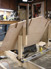
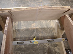
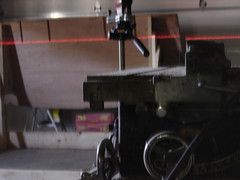
Laser Leveling the Rear Transom
In preparation of mounting the front transom, we used a laser level to make sure the rear transom was mounted correctly. The mounting of the front transom started immediately following this verification.
Monday, April 25, 2005
Still Pluggin' away
The last two weeks have been a little less action and a little more thought. We finished up the sacrificial frame pieces and have started mounting the front transom. Since this is a precise process, we've put a lot of thought into the process, but haven't made much noticeable progress. The key through all of this though, is to make sure we keep on keepin' on.
Sunday, April 10, 2005
BoatBuilding - Cutting the Frames
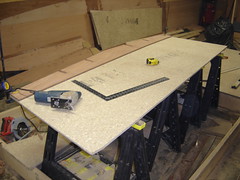
Over the last couple of weeks, we've been constructing temporary frame pieces, which we're cutting out of particle board. The reason we're doing this, and the process behind what we're doing will take a little bit of explaination, so be prepared for a long entry.
The reason we're cutting these temporary frame pieces is so that we're sure the hull is straight. If you look at the picture, you may notice two pieces of board... one smaller piece of board, sitting on top of the particle board. The smaller piece is the actual frame piece that will be in the boat when it's put on the water. The hull goes much farther up than this though, so we are using temporary pieces during the hull setting process. Once the hull is set, we will remove the temporary pieces and install the permanent pieces, so that we can add the deck.
In order to cut these sacrificial particle board frame pieces, we started with a 4x8 piece of particle board. We set the actual frame piece on the particle board and clamped it in place. We then determined the center point and line of the actual frame piece and extended this center line through the particle board, so that we could measure needed dimensions. After measuring the center line, we extended the end-lines of the permanent frame piece up the particle board, and measured from the center line to the top corners. In order to make sure our cuts were true, we measured cross-angle. we then added the notches and cut it all out with a power saw, except for the notches, where we used a jigsaw.
Click here to see the video summary of what we did.
Subscribe to:
Posts (Atom)